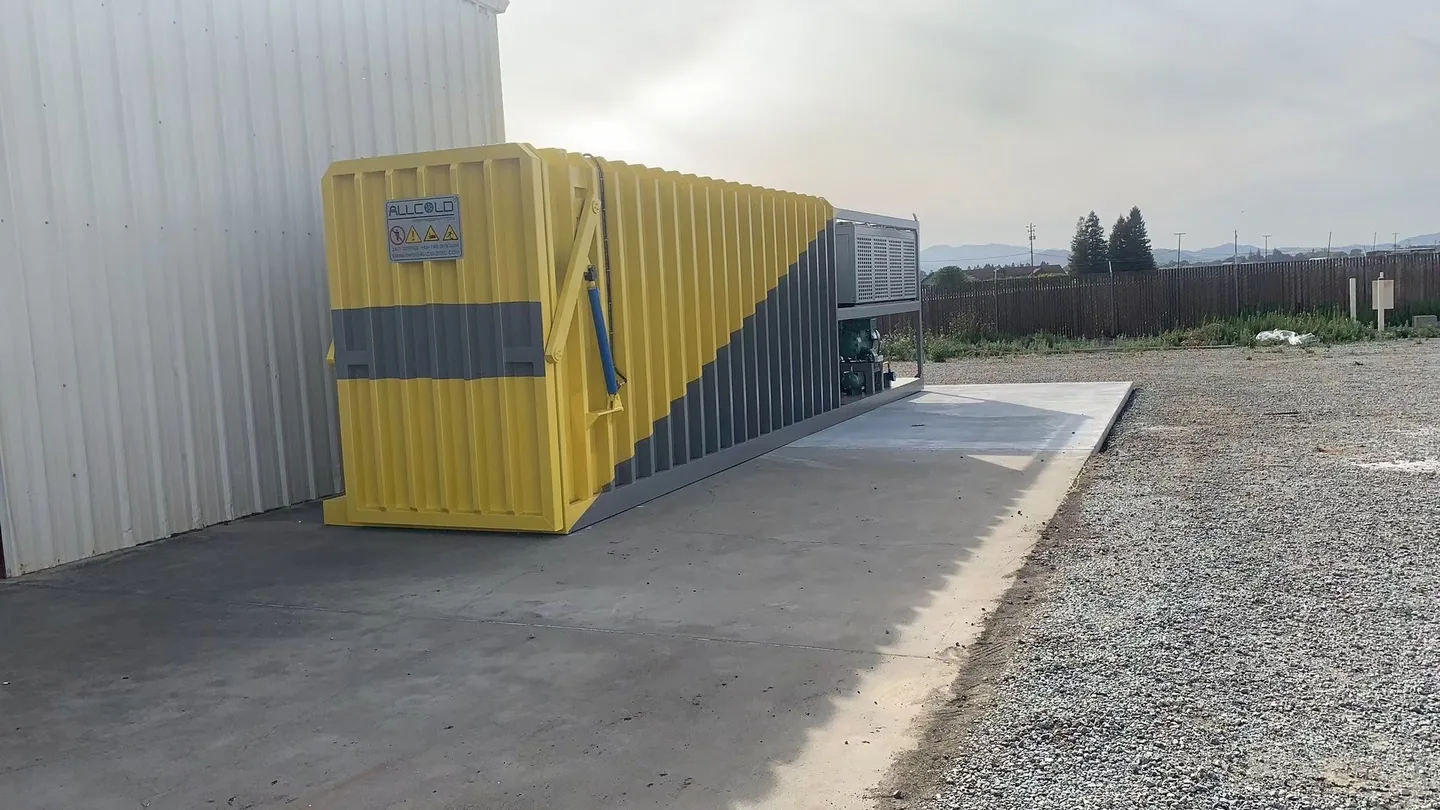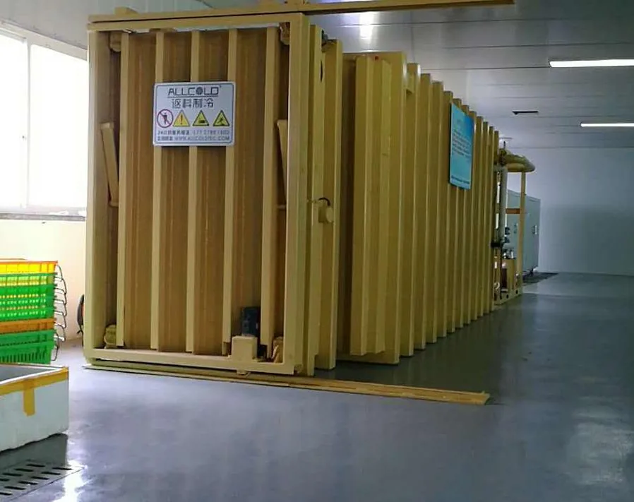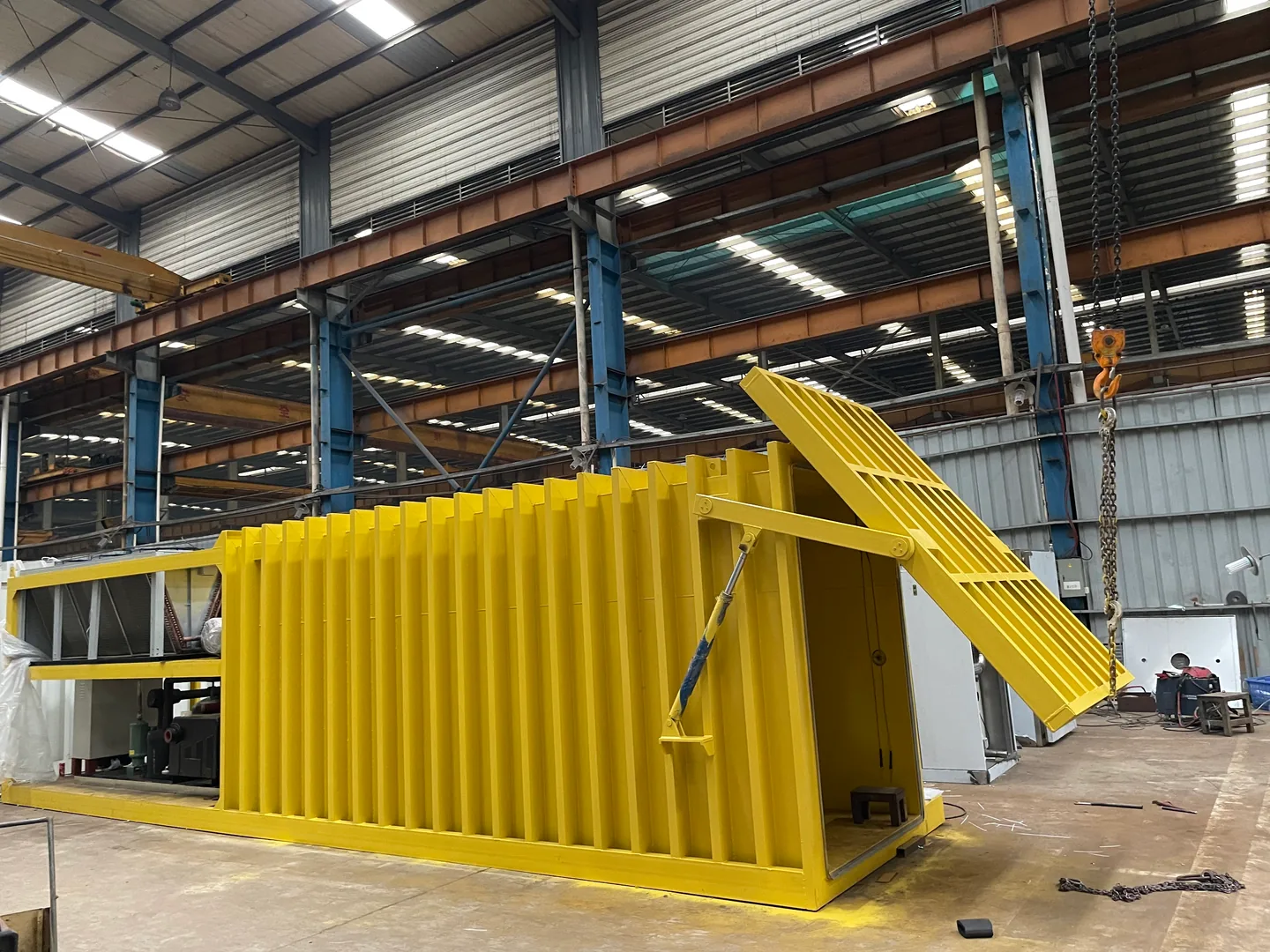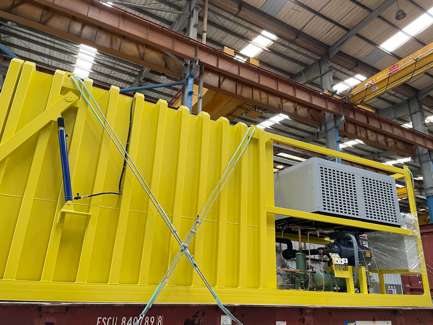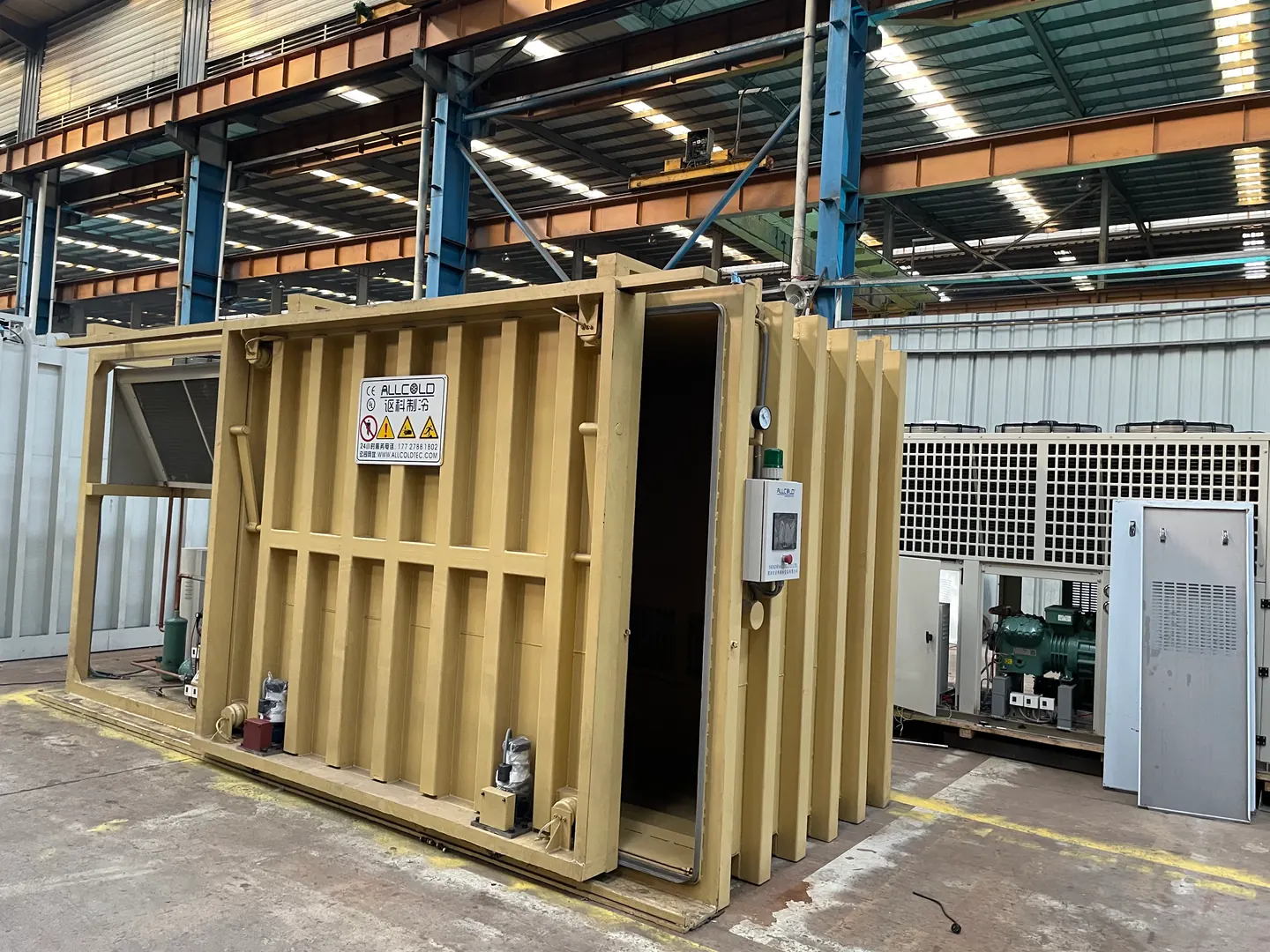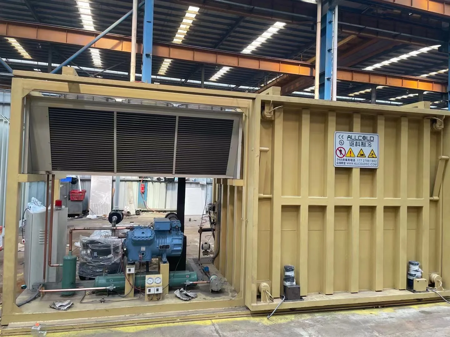
ALLCOLD · EQUIPMENT LAYOUT
The best place to load a vacuum cooler is not always the best place for its machinery. Plan the connections before you commit to either location.
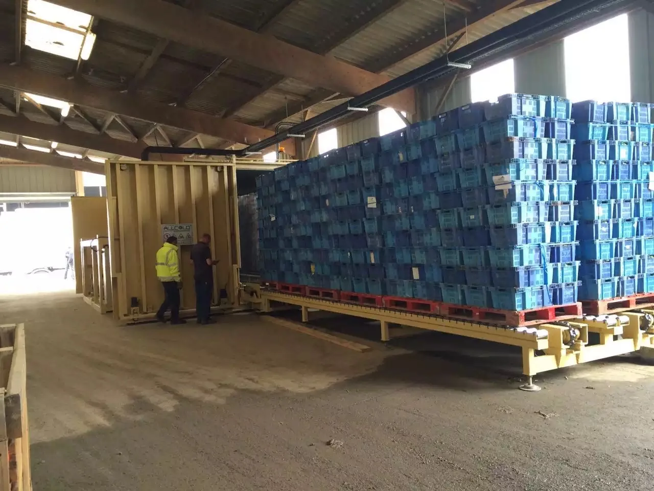
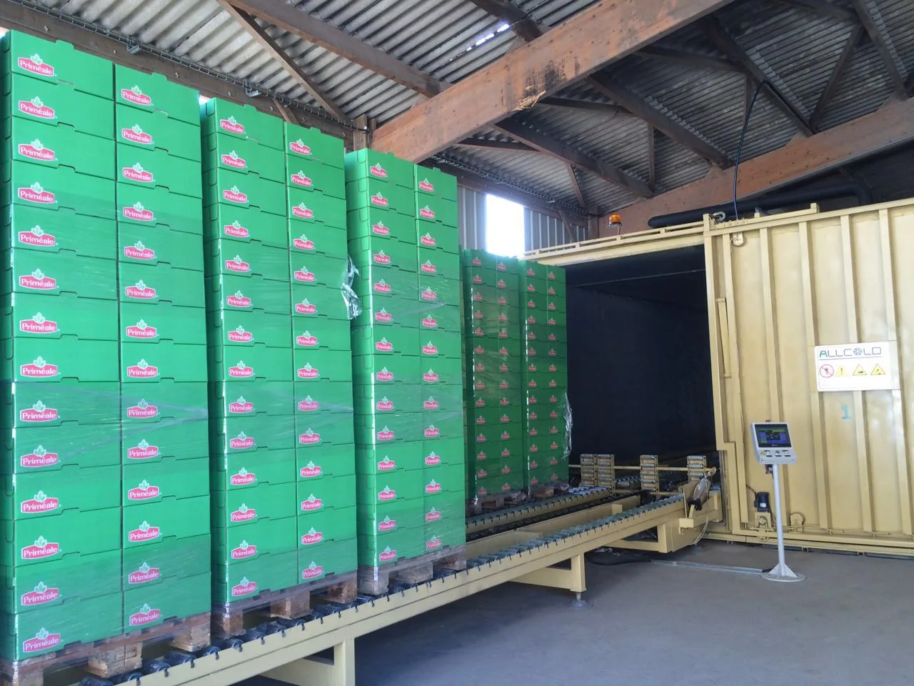
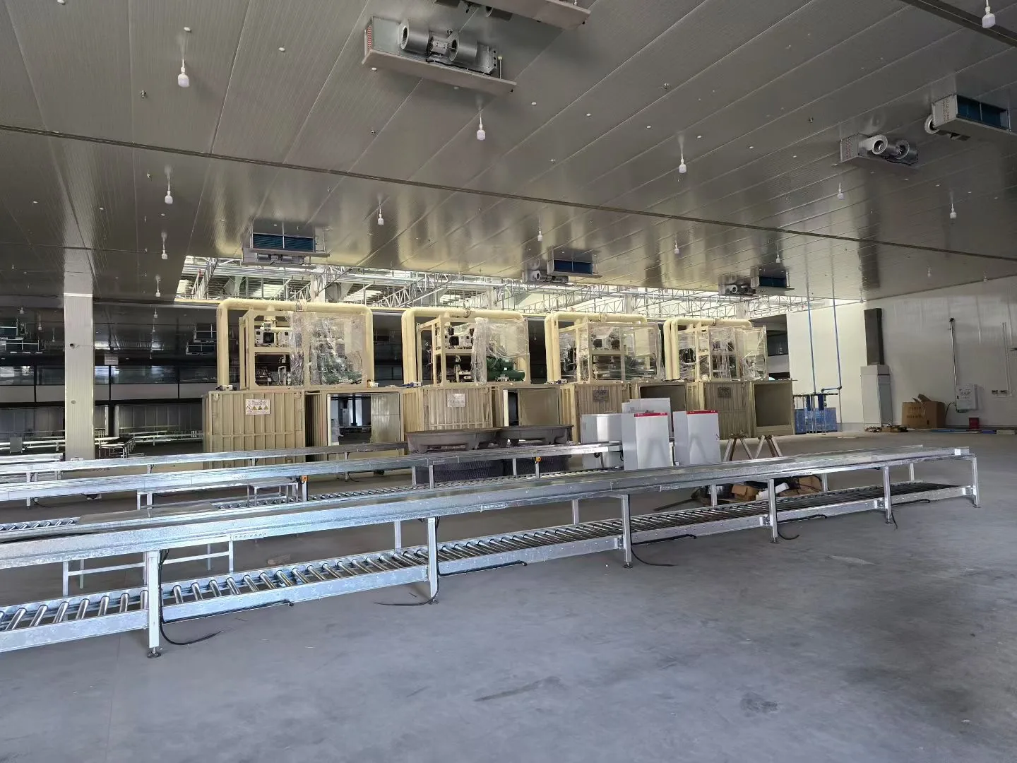
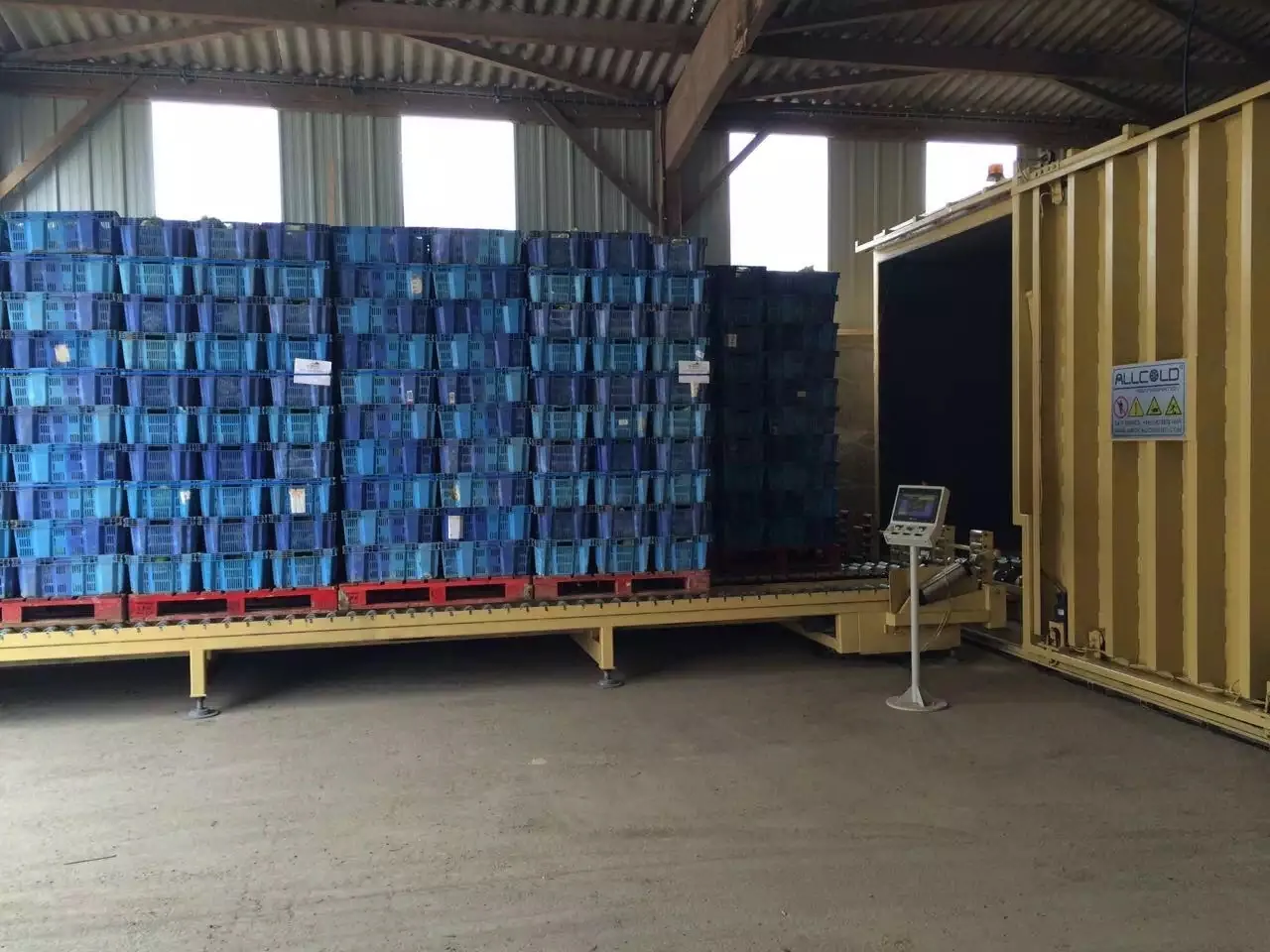
You have found room for the vacuum chamber beside your production line. The proposed system also includes a vacuum unit and a chiller—but placing everything together would block a trolley route or consume valuable working space. Can those units go through the wall into another room?
Yes, a split arrangement can be considered for a system designed for it. However, the chamber, vacuum equipment and chiller cannot simply be moved apart without checking their connections. The supplier needs to approve the actual layout, pipe routes, operating conditions and installation scope. There is no single maximum separation distance that applies to every vacuum cooler.
This guide focuses on systems with separately located equipment, including configurations that use a water or glycol chiller. It does not assume every vacuum cooler has three independent units, or that an existing integrated machine can be converted.
Before you approve the layout
- Identify the connection. Is the proposed route a vacuum line, a circulating liquid loop, a refrigerant line, or electrical and control cabling?
- Draw the real route. Show bends, wall crossings, changes in height and service access—not only the straight-line distance between units.
- Agree who supplies and checks it. Ask which site-installed items are included, who approves the design and who verifies operation after connection.
1. Identify what is being separated
“Can we move the chiller?” sounds precise, but it can describe different changes. Moving a complete packaged chiller with a circulating liquid connection is not the same proposal as relocating a refrigerant condenser. Likewise, relocating the vacuum unit changes a different part of the system.
Start with a labelled equipment arrangement and a connection diagram. Ask the supplier to show the chamber, vacuum equipment, vapour-handling equipment where fitted, refrigeration components and any external utilities. The diagram should identify the medium in each connecting pipe.
| Connection | What to establish | What not to assume |
|---|---|---|
| Vacuum line | Its endpoints, vapour-handling arrangement, proposed pipe geometry and supplier-approved design. | That the pump’s nameplate capacity will be available unchanged at the chamber. |
| Water or glycol supply and return | Required liquid, temperatures, flow, available pump pressure and the complete circulation route. | That matching the chiller’s cooling-capacity label establishes compatibility. |
| Refrigerant lines, if applicable | Whether field-installed refrigerant piping is part of the proposed design, and who specifies and installs it. | That it can be treated like a water connection or extended without review. |
| Power, controls and other utilities | Connection points, cable routes, operator controls and any additional services required by the selected configuration. | That separating the mechanical units leaves all electrical and control work unchanged. |
Keep the two uses of “condenser” clear. A water-vapour condenser in the vacuum process and a refrigerant condenser in the refrigeration circuit perform different jobs. Before comparing a “standard” and a “plate” component, ask which component and circuit the supplier means. A photograph or short quotation label is not enough to settle that question.
For the available application paths, see Allcold’s vacuum coolers for cooked food and bakery production. Confirm the arrangement for the quoted configuration rather than borrowing a layout from another model.
2. Why the route matters more than one distance
A floor plan may show the machinery only a few metres from the chamber. The installed connections may still travel up a wall, over a corridor, around an obstruction and down again. Ask for both the equipment positions and the intended routing.
For vacuum pipework, check the complete flow path
Vacuum pipes, bends and valves affect conductance: how readily gas passes through the connection. Leybold explains that conductance depends on geometry, pressure and flow conditions.[1] This is why a pump rating alone cannot approve a remote position. Ask the supplier to assess the proposed path at the required operating duty, including the components between the chamber and pump.
The useful question is not “Will a larger pump solve the extra distance?” It is “Does this assembled system meet the agreed cooling duty with this approved route?” Our guide to pump capacity and cooling time explains the distinction.
For a liquid loop, check circulation as well as cooling capacity
Thermal Care’s glycol-chiller guidance highlights correctly sized piping, restricted fittings and the need to review overhead routing for shutdown backflow.[2] For a proposed vacuum-cooling installation, ask for the required flow and the pump’s available pressure at that flow. Have the supplier and installer check the entire supply-and-return circuit, not just one pipe length.
Record elevation changes even if the equipment is on the same floor. Whether those changes affect filling, shutdown behaviour or pumping requirements depends on the circuit design; do not select a pump from elevation alone.
Moving heat out of production still requires a destination
For an air-cooled chiller, a separate room needs an adequate airflow arrangement. Thermal Care warns against confined positioning and emphasises airflow and maintenance clearance.[2] Use the selected equipment’s requirements rather than copying another manufacturer’s clearance dimensions. An outdoor position also needs an appropriate equipment specification; it is not approved simply because it frees indoor space.
For broader site conditions, refer to our outdoor installation guide. Keep this decision separate from the approval of the connecting route.
3. Compare three layout options before choosing
Ask for alternatives while the layout is still a drawing. A useful comparison holds the product, batch load and cooling target constant, then changes only the proposed arrangement and its associated installation work.
| Option | Reason to consider it | Main question before approval |
|---|---|---|
| Equipment grouped near the chamber | A candidate where a compact installation and convenient access to connections are priorities. | Will the machinery, service space and loading route all fit without obstructing production? |
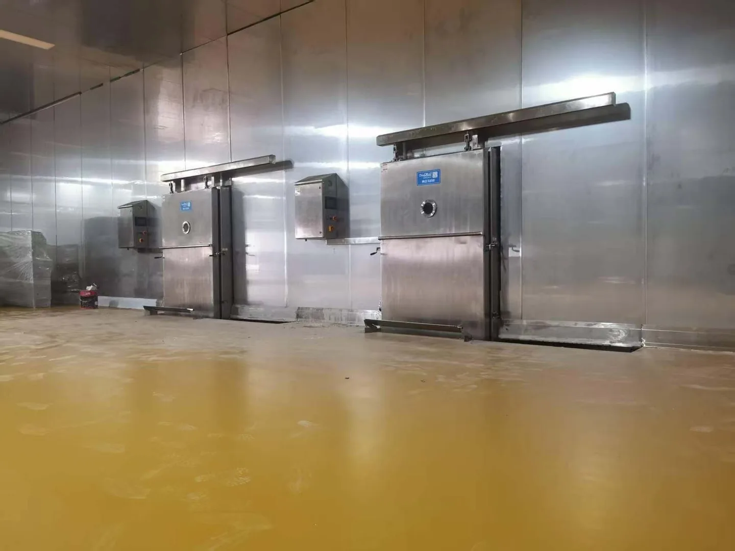
| Chamber beside production; machinery in an adjacent room | A candidate where product handling and machinery access need separate spaces. | Can the wall crossings, connecting routes and machinery-room conditions be approved? |
| Chamber inside; selected equipment outside | A candidate where external space is available for suitable equipment. | Does the proposal include the required outdoor specification, site work and route protection? |
These are planning options, not a ranking. A split arrangement may recover useful production-floor area without reducing the total installed footprint: the remote equipment, service space and pipe route still occupy space somewhere.
An example of a better layout question
Imagine a food producer who wants the chamber beside the trolley staging area and has a spare room behind the wall. This is an illustrative scenario, not an Allcold project result.
Instead of asking whether the spare room is “close enough,” the buyer marks two possible wall crossings, the full connection route, room ventilation, access doors and the location from which operators will use the controls. The supplier can then compare the adjacent-room proposal with a grouped arrangement and identify what each quotation includes.
The outcome to request is a reviewed arrangement with stated conditions—not a verbal assurance that the distance should be fine.
If reducing noise is the objective, specify the location that matters: a packing bench, operator station or neighbouring room. Do not assume a wall will deliver a particular reduction. The vacuum cooler noise-planning guide covers how to frame that assessment.
4. Define installation responsibilities before ordering
The equipment price and the installed split system are not necessarily the same scope. Two quotations can describe similar machinery while leaving very different amounts of field work to the buyer.
Request a simple responsibility schedule. For each item below, identify the design approver, supplier, installer and person responsible for checking the finished work:
- Interconnecting pipes, fittings, valves, supports and insulation where required.
- Wall penetrations, sealing, equipment bases and protection of the route.
- Power supply, disconnects, control cabling and specified interfaces.
- Ventilation, drainage and outdoor protection where applicable.
- Initial filling, connection checks, startup support and operating checks.
Define the boundary explicitly—for example, whether the equipment supplier provides connection sizes only, a reviewed piping design, or the complete connecting materials. Avoid accepting “installation by others” as the entire explanation.
Keep the approved drawing revision with the order. If the contractor later moves the machinery or reroutes connections around an obstruction, obtain a review before treating the changed arrangement as equivalent. That is particularly important when the agreed performance depends on specified site conditions.
5. Send a brief that makes the layout review useful
You do not need a finished construction drawing to start the discussion. A dimensioned sketch and clear site photographs can identify the questions that need engineering attention.
- Product duty: product types, net weight per batch, starting and target temperatures, and intended operating schedule.
- Loading: full trolley or pallet dimensions, quantity per batch, loading direction and staging area.
- Locations: proposed chamber, vacuum-unit and chiller positions, with each room or outdoor area identified.
- Routes: approximate pipe runs, major bends, elevation changes, wall crossings and obstacles.
- Conditions: ambient-temperature range, ventilation, utilities, drainage and indoor or outdoor exposure.
- Project scope: who will handle local installation and whether an existing chiller or other shared utility is proposed.
Ask for this response: “Please identify which components can be located separately, review the proposed routes, and state the connection requirements, operating conditions, installation exclusions and any configuration changes needed.”
6. Common buyer questions
How far away can the vacuum pump or chiller be?
There is no universal distance. Provide the actual route and equipment duty so the supplier can assess each connection. A limit for one configuration should not be reused for another.
Can I use the chiller already installed in my factory?
It is a proposal to evaluate, not an automatic saving. Supply its model and operating data, the available capacity while other equipment is running, liquid type and temperature, flow and pump information. Ask the vacuum-cooler supplier to confirm compatibility and how the two systems will operate together.
Will splitting the equipment make cooling slower?
Separation alone does not establish the result. Ask for the agreed cooling duty to be assessed against the complete approved configuration, including the connections. Do not compare one supplier’s grouped arrangement with another’s remote arrangement as though the installation conditions were identical.
Can an installed integrated machine be separated later?
Do not assume so. Give the manufacturer the serial number, existing configuration and proposed changes. Moving an integrated unit’s components is a modification assessment, not merely a furniture-layout decision.
Keep the product route convenient—and make the equipment route workable
Send Allcold your production requirements, a simple floor plan and the proposed equipment positions. Ask us to review whether a split arrangement is suitable and what must be included in the quotation before you fix the installation layout.
Technical references
These references support general component-planning principles, not a universal Allcold pipe length, clearance or performance rating.
- Leybold — How is conductance in vacuum calculated? Geometry, pressure and flow conditions in vacuum connections. ↩
- Thermal Care — Glycol Chillers Prep Guide Piping, overhead-route considerations, airflow and service access. Equipment-specific dimensions and fluid recommendations are not adopted as Allcold specifications. ↩ ↩